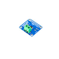
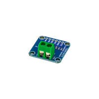
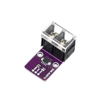
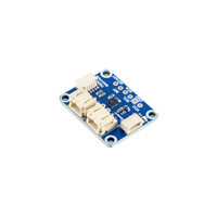
Precision Power Monitoring with Built-In Overcurrent Detection: Enhance Your Power Systems with Reliable, Isolated Sensing Technology
The ACS71020 Hall-effect Power Monitoring and Overcurrent Detection Breakout is engineered to provide a high-accuracy, isolated power measurement solution tailored for demanding industrial and high-power applications. Designed with integrated 16-bit ADCs for both voltage and current, it ensures precise real-time monitoring, while reinforced electrical isolation up to 517 VRMS eliminates the need for additional isolated supplies. This module supports both I2C and SPI communication protocols, allowing flexible integration into embedded systems and microcontroller-based applications.
With a current-sensing range from 0 to 90A, this breakout board is ideal for tracking electrical load performance, energy consumption, and detecting overcurrent conditions. Its built-in features, such as temperature compensation, offset correction, and overvoltage/undervoltage monitoring, make it a reliable component for power analysis and fault detection. The module also supports key power metrics, including active, reactive, and apparent power as well as RMS and instantaneous measurements.
Key Features and Benefits
-
Wide Current Sensing Range: Measures currents from 0 to 90A, suitable for both low and high power systems
-
Dual Communication Interface: Seamless connection via I2C or SPI for maximum design flexibility
-
High-Precision 16-bit ADCs: Delivers accurate voltage and current measurements for reliable power data
-
Advanced Power Analysis: Calculates active, reactive, and apparent power, as well as power factor
-
Electrical Isolation: Reinforced isolation up to 517 VRMS, eliminating the need for dual isolated supplies
-
Fault Detection Features: Overcurrent fault output pin and programmable voltage threshold alerts
-
Temperature Resilience: Operates across a wide temperature range, ideal for harsh industrial settings
-
Zero Crossing Detection: Dedicated pin for voltage zero crossing enhances phase control applications
-
Hall-Effect Sensing: Offers common-mode stray field rejection for superior signal integrity
-
User Programmability: Configure under/overvoltage conditions and thresholds based on application needs
The transmission of data over I2C is composed of several steps outlined in the sequence below.
-
Start Condition: Defined by a negative edge of the SDA line, initiated by the Master while SCL is high.
-
Address Cycle: 7-bit Slave address, plus 1 bit to indicate write (0) or read (1), followed by an Acknowledge bit.
-
Data Cycles: Reading or writing 8 bits of data, followed by an Acknowledge bit. This cycle can be repeated for multiple bytes of data transfer. The first data byte on a write could be the register address.
-
Stop Condition: Defined by a positive edge on the SDA line while SCL is high.
- ACS71020 Datasheet
- ACS71020 Power Monitoring Application Notes with Arduino Source Code
- ACS71020 I2C Addressing Using Application Notes
- ACS71020 Power Monitoring Breakout 3D STEP File
ACS71020 Power Monitoring Breakout Dimensions

- Current Sensing Range:
- 0 to 90 A
- Interface:
- I2C or SPI
- ADC:
- 16-bit voltage and current ADCs


