1 IMAGE
Smart 9-DOF IMU with integrated accelerometer, gyroscope, and magnetometer.
Smart 9-DOF IMU with integrated accelerometer, gyroscope, and magnetometer.
 7Semi • I²C • DOF • IMU
Smart 9-axis orientation sensing with built-in sensor fusion, Qwiic I2C connectivity, and ready-to-use motion outputs.
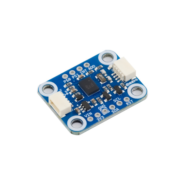
The 7Semi BNO055 9-DOF Absolute Orientation Sensor Breakout I2C Qwiic is an intelligent motion sensing module based on the Bosch BNO055 sensor. It combines a 3-axis accelerometer, gyroscope, magnetometer, and onboard sensor fusion processor to provide ready-to-use orientation data, including Euler angles, quaternions, gravity vectors, and linear acceleration. Featuring a Qwiic-compatible I²C interface, the module offers easy integration with Arduino, ESP32, STM32, Raspberry Pi, and other microcontrollers. Its built-in sensor fusion significantly reduces development complexity, making it ideal for robotics, motion tracking, navigation, wearables, drones, and industrial automation applications.
| Parameter | Value |
|---|---|
| Category of product | 9-DOF IMU |
| Sensor used | Bosch BNO055 |
| Accelerometer | ±2g, ±4g, ±8g, ±16g |
| Gyroscope Range | ±125°/s to ±2000°/s |
| Magnetometer Range | ±1300 µT X/Y, ±2500 µT Z typical |
| Operating Temperature | -40°C to +85°C |
| Supply voltage required | 3.3V |
| Applications | Robotics, drones, wearables, VR/AR, navigation, motion tracking |
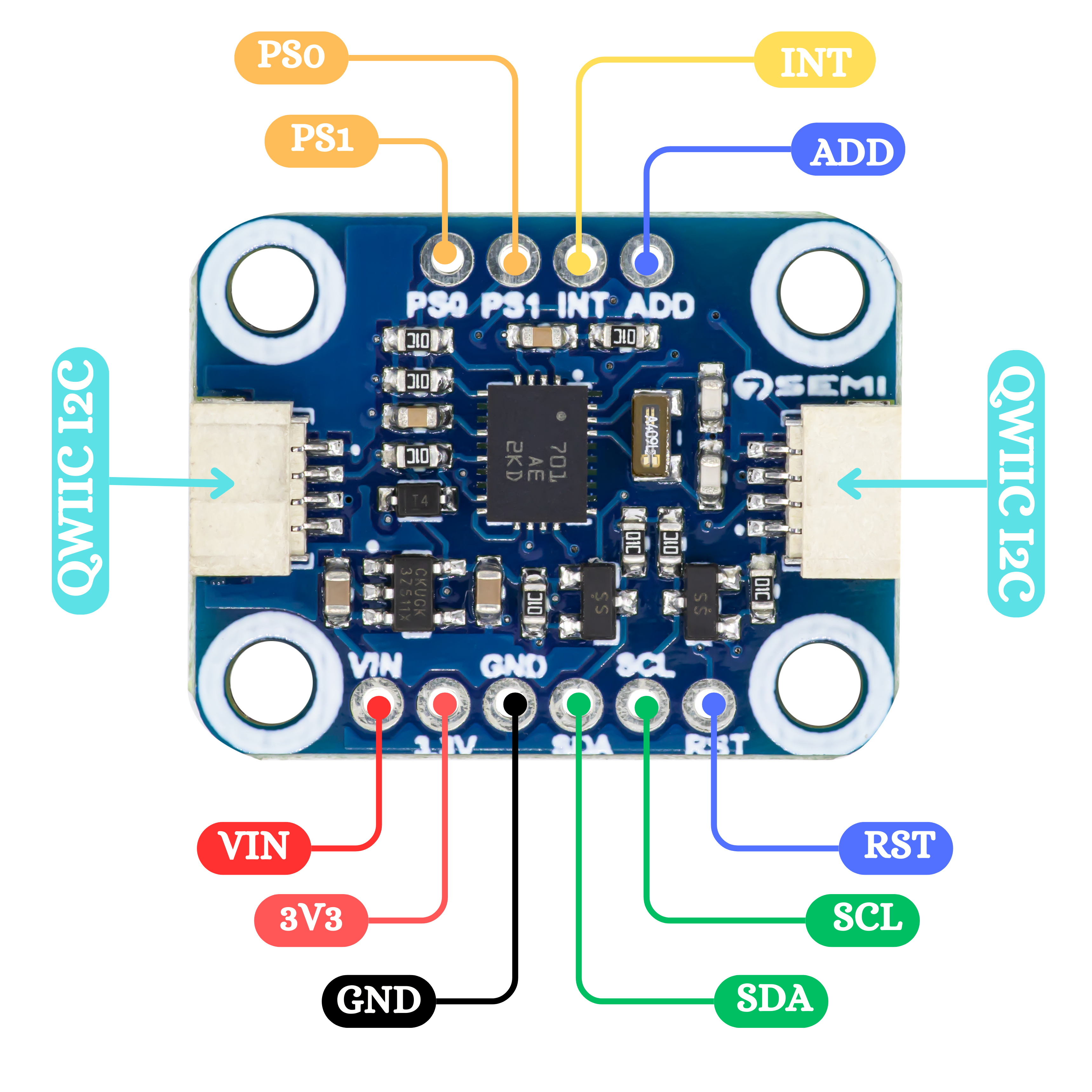
| # | Pin | Description |
|---|---|---|
| 1 | 3V3 | Power 3.3–5 V |
| 2 | GND | Ground |
| 3 | SDA | I²C Data |
| 4 | SCL | I²C Clock |
| 5 | ADD | Address select |
| 6 | INT | Interupt output |
| 7 | PS1 | Protocol select 1 |
| 8 | PS0 | Protocol select 0 |
| 9 | VIN | Power input |
| 10 | RST | Reset |
/***************************************************************
* @file Basic.ino
* @brief Comprehensive example for the 7Semi BNO055 IMU sensor
* demonstrating orientation, raw data, calibration, and
* quaternion features via I2C.
*
* Features demonstrated:
* - Initialization and NDOF mode selection
* - Reading Euler angles (heading, roll, pitch)
* - Reading raw accelerometer, gyroscope, magnetometer data
* - Reading linear acceleration and gravity vector
* - Reading quaternion data
* - Reading temperature and calibration status
*
* Sensor Configuration:
* - Operation Mode : NDOF (Fusion mode)
* - I2C Address : Auto-detect (0x28 or 0x29)
* - External Crystal: Enabled
*
* Connections:
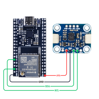
* - VIN -> 3.3V / 5V
* - GND -> GND
* - SDA -> A4 (Uno) or custom SDA pin
* - SCL -> A5 (Uno) or custom SCL pin
* - ADR -> GND (for 0x28) or VCC (for 0x29)
*
* Library : 7Semi_BNO055
* Author : 7Semi
* Version : 1.0
* Date : 19 September 2025
* License : MIT
***************************************************************/
#include <Wire.h>
#include <7Semi_BNO055.h>
BNO055_7Semi imu;
void printCalib() {
uint8_t sys, gyr, acc, mag;
imu.calibBreakdown(sys, gyr, acc, mag);
Serial.print(F("Calib SYS:"));
Serial.print(sys);
Serial.print(F(" G:"));
Serial.print(gyr);
Serial.print(F(" A:"));
Serial.print(acc);
Serial.print(F(" M:"));
Serial.println(mag);
}
void setup() {
Serial.begin(115200);
delay(500);
Serial.println(F("\nBNO055 demo"));
// Initialize (Wire, address, use external crystal)
if (!imu.begin()) {
Serial.println(F("ERROR: BNO055 not found"));
while (1) { delay(1000); }
}
imu.setMode(Mode::NDOF);
// Optional: wait for calibration
Serial.print(F("Calibrating"));
if (!imu.waitCalibrated(10000, 200)) {
Serial.println(F(" - timeout"));
} else {
Serial.println(F(" - done"));
}
printCalib();
Serial.println(F("Ready!\n"));
}
void loop() {
// // Orientation (degrees or radians depending on UNIT_SEL; defaults to degrees)
float heading, roll, pitch;
if (imu.readEuler(heading, roll, pitch)) {
Serial.print(F("Euler H/R/P: "));
Serial.print(heading, 1);
Serial.print('\t');
Serial.print(roll, 1);
Serial.print('\t');
Serial.println(pitch, 1);
}
// Raw sensor data
int16_t ax, ay, az, gx, gy, gz, mx, my, mz;
if (imu.readAccel(ax, ay, az)) {
Serial.print(F("Accel raw: "));
Serial.print(ax);
Serial.print(", ");
Serial.print(ay);
Serial.print(", ");
Serial.println(az);
}
if (imu.readGyro(gx, gy, gz)) {
Serial.print(F("Gyro raw : "));
Serial.print(gx);
Serial.print(", ");
Serial.print(gy);
Serial.print(", ");
Serial.println(gz);
}
if (imu.readMag(mx, my, mz)) {
Serial.print(F("Mag raw : "));
Serial.print(mx);
Serial.print(", ");
Serial.print(my);
Serial.print(", ");
Serial.println(mz);
}
// Optional: linear acceleration / gravity
int16_t lx, ly, lz, gxv, gyv, gzv;
if (imu.readLinear(lx, ly, lz)) {
Serial.print(F("LinAcc raw: "));
Serial.print(lx);
Serial.print(", ");
Serial.print(ly);
Serial.print(", ");
Serial.println(lz);
}
if (imu.readGravity(gxv, gyv, gzv)) {
Serial.print(F("Grav raw: "));
Serial.print(gxv);
Serial.print(", ");
Serial.print(gyv);
Serial.print(", ");
Serial.println(gzv);
}
// Optional: quaternion
float qw, qx, qy, qz;
if (imu.readQuat(qw, qx, qy, qz)) {
Serial.print(F("Quat WXYZ: "));
Serial.print(qw, 4);
Serial.print(", ");
Serial.print(qx, 4);
Serial.print(", ");
Serial.print(qy, 4);
Serial.print(", ");
Serial.println(qz, 4);
}
int temp = imu.temperatureC();
Serial.print("Temperature: ");
Serial.print(temp);
Serial.println(" °C");
// Show calibration every ~2s
static uint32_t tCal = 0;
if (millis() - tCal > 2000) {
tCal = millis();
printCalib();
}
Serial.println();
delay(500);
}
Yes. It provides fused orientation data such as Euler angles and quaternions directly from the sensor.
The common default I2C address is 0x28. The alternate address is 0x29 when configured using the address pin.
Yes. It works with ESP32 ,AVR ,STM using I2C communication.