1 IMAGE
ESP32 based EC200U Modem
ESP32 based EC200U Modem
 EC200U | ESP32-S3 | GPS
Compact, production-ready embedded hardware module.
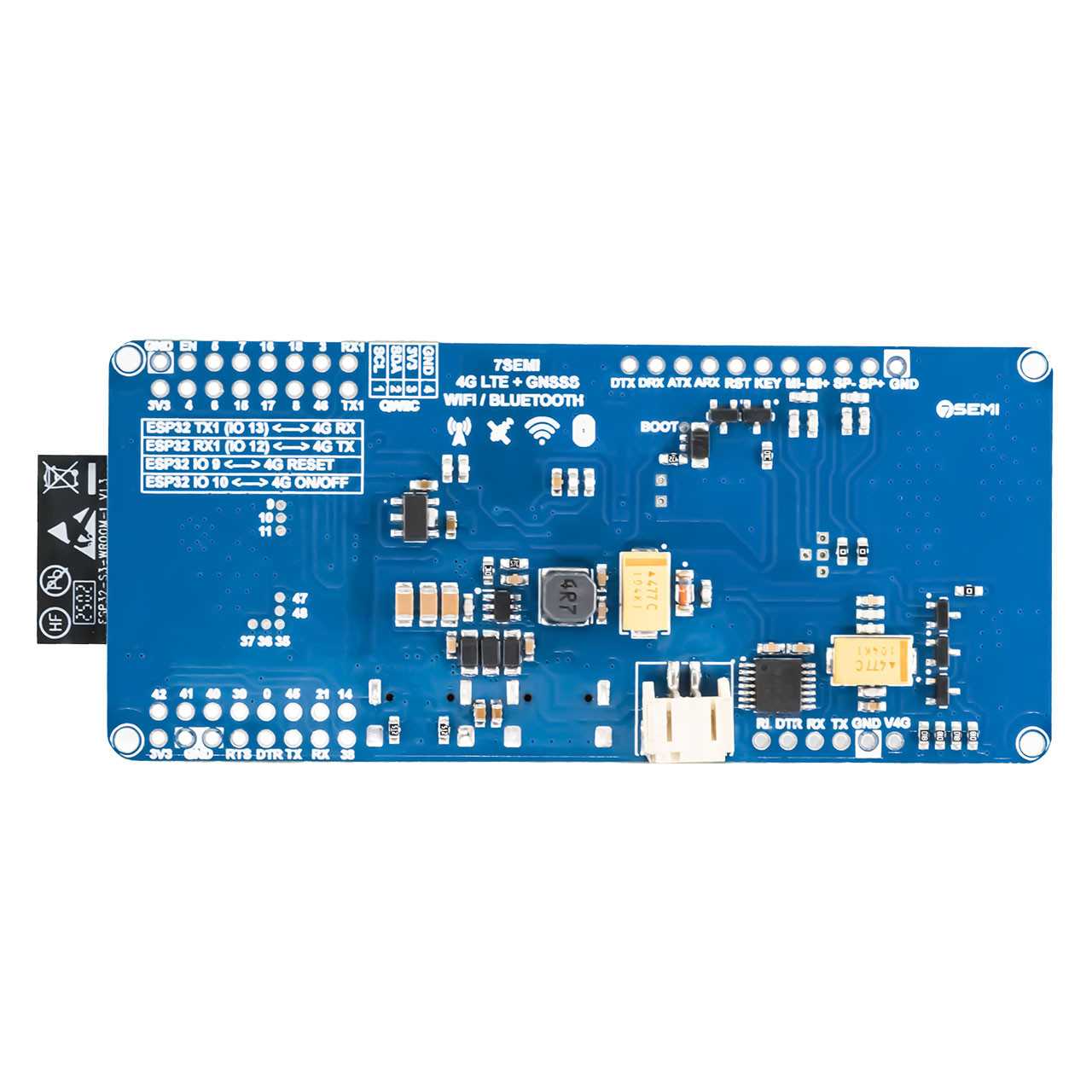
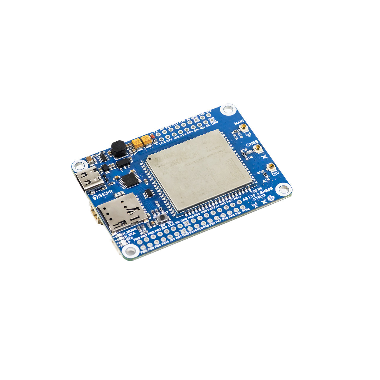
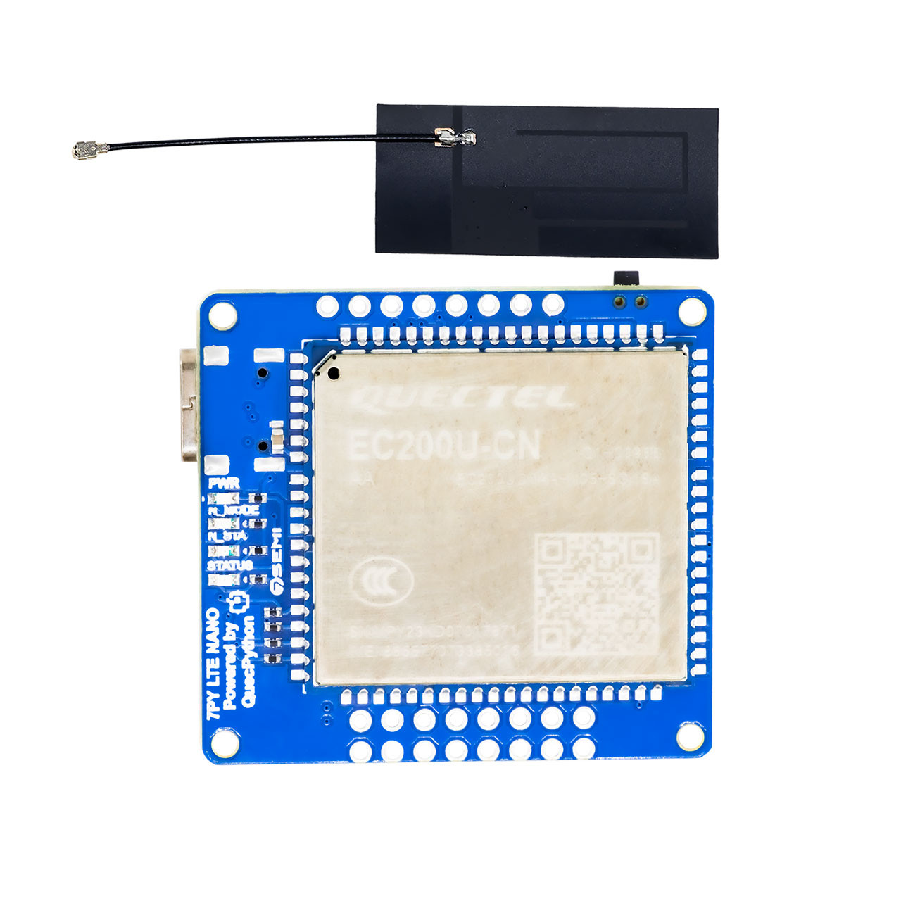
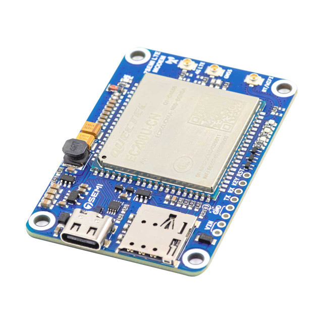
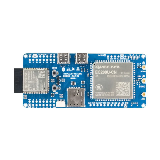
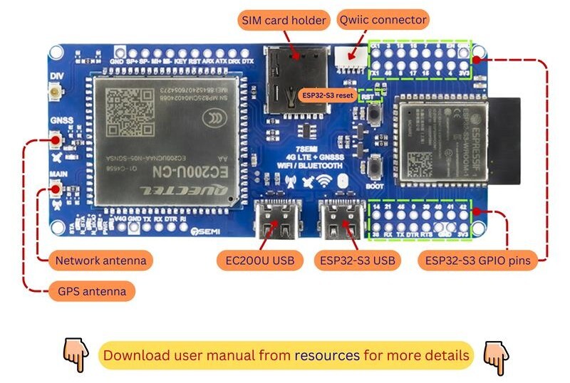
The 7Semi ESP32-S3 EC200U 4G LTE Cat-1 WiFi Bluetooth GNSS IoT Smart Modem combines the powerful ESP32-S3 microcontroller with the Quectel EC200U LTE Cat-1 modem, providing a complete platform for IoT, remote monitoring, telemetry, tracking, and industrial automation applications. With integrated 4G LTE, Wi-Fi, Bluetooth, and multi-constellation GNSS support, the board enables reliable long-range communication, precise location tracking, and seamless wireless connectivity from a single compact device. The ESP32-S3 handles application processing and peripheral interfacing, while the EC200U modem provides cellular connectivity for cloud communication, SMS services, and remote device management. Supporting GPS, GLONASS, BeiDou, Galileo, and QZSS navigation systems, the modem is ideal for asset tracking, fleet management, smart agriculture, logistics, and location-aware IoT solutions. Built-in Wi-Fi and Bluetooth further simplify local device configuration, wireless networking, and sensor integration. Designed for developers, system integrators, and industrial users, the 7Semi ESP32-S3 EC200U Smart Modem offers a flexible and powerful foundation for building connected products that require cellular communication, wireless connectivity, and real-time positioning capabilities.

| Parameter | Value |
|---|---|
| Product name | 7Semi ESP32-S3 EC200U 4G LTE Cat-1 WiFi Bluetooth GNSS IoT Smart Modem |
| Main controller | ESP32-S3 Dual-Core Xtensa® LX7 Microcontroller |
| Cellular Modem | Quectel EC200U-CN LTE Cat-1 Module |
| Network support | LTE-FDD, LTE-TDD, GSM/GPRS |
| LTE-FDD Bands | Up to 10 Mbps Downlink, Up to 5 Mbps Uplink |
| LTE-TDD Bands | Up to 8.96 Mbps Downlink, Up to 3.1 Mbps Uplink |
| Wifi | 2.4 GHz Wi-Fi |
| GNSS Support | GPS, GLONASS, BeiDou, Galileo, QZSS |
| Supply Voltage | Typicaly 3.3V |
| Operational temprature | -40°C to +85°C |
| Dimension in mm | 98 x 40 x 10 |
| Application | Industrial IoT, Remote Monitoring, Asset Tracking, Smart Agriculture, Fleet Management, Smart City Infrastructure, Telemetry Systems |
#define EC200_RESET_PIN   9
#define EC200_PWRKEY_PIN  10

void EC200_GPIO_Init()
{
    pinMode(EC200_RESET_PIN, OUTPUT);
    pinMode(EC200_PWRKEY_PIN, OUTPUT);

    digitalWrite(EC200_RESET_PIN, LOW);
    digitalWrite(EC200_PWRKEY_PIN, HIGH);
}
void EC200_PowerOn()
{
    digitalWrite(EC200_PWRKEY_PIN, HIGH);
    delay(3000);
    digitalWrite(EC200_PWRKEY_PIN, LOW);
}
void EC200_Reset()
{
    digitalWrite(EC200_RESET_PIN, HIGH);

    delay(250);
    digitalWrite(EC200_RESET_PIN, LOW);
}
// Serial3 pins for GSM module
#define RXD1 12
#define TXD1 13
#define GSM_BAUD 115200

unsigned long lastAT = 0;

void setup() {
  Serial.begin(115200);
  Serial.println("\nESP32-S3 WiFi + GSM Network Strength Test");

  // Start Serial1 for GSM
  Serial1.begin(GSM_BAUD, SERIAL_8N1, RXD1, TXD1);
  delay(2000);

  // Test GSM communication
  sendAT("AT");        // Test communication
  sendAT("AT+CPIN?");  // SIM status
  sendAT("AT+CREG?");  // Network registration

  // Check network registration and signal strength
  checkNetwork();

  // Example: send SMS
  sendSMS("+918655821342", "Hello from ESP32-S3 via GSM!");

  // Example: make a call
  makeCall("pHONE NUMBER ");
}

void loop() {
  // Relay GSM responses to Serial monitor
  while (Serial1.available()) {
    Serial.write(Serial1.read());
  }

  // Periodically check network registration and signal86
  if (millis() - lastAT > 15000) {  // every 15 seconds
    sendAT("AT+CREG?");
    readCallStatus();  // Check call status
    checkNetwork();
    lastAT = millis();
  }
}
// ===== Send AT command and print response =====
void sendAT(const String &cmd) {
  Serial.print("Sending: ");
  Serial.println(cmd);
  Serial1.print(cmd + "\r");

  String response = "";
  unsigned long start = millis();
  while (millis() - start < 1000) {  // wait up to 1 second for response
    while (Serial1.available()) {
      response += (char)Serial1.read();
    }
  }

  response.trim();
  if (response.indexOf("ERROR") != -1) {
    Serial.println("ERROR: AT command failed -> " + cmd);
  } else {
    Serial.println("Response: " + response);
  }
  Serial.println();
}

// ===== Check GSM network registration and signal strength =====
void checkNetwork() {
  Serial.println("Checking GSM network...");
  sendAT("AT+CREG?");
  sendAT("AT+CSQ");
}

// ===== Send SMS =====
void sendSMS(const String &number, const String &message) {
  Serial.println("Sending SMS...");

  sendAT("AT+CMGF=1"); // Text mode

  Serial1.print("AT+CMGS=\"" + number + "\"\r");
  delay(500);
  while (Serial1.available()) Serial.write(Serial1.read());
  Serial1.print(message);
delay(500);
  Serial1.write(26); // Ctrl+Z to send
  delay(3000);
  while (Serial1.available()) Serial.write(Serial1.read());
  Serial.println("SMS command sent\n");
}
// ===== Make a call =====
void makeCall(const String &number) {
  Serial.println("Dialing number: " + number);
  Serial1.print("ATD" + number + ";\r"); // semicolon for voice call
  delay(500);
  while (Serial1.available()) Serial.write(Serial1.read());
  Serial.println("Call command sent\n");
}
// ===== Hang up call =====
void hangUp() {
  Serial.println("Hanging up call...");
  sendAT("ATH");
}

// ===== Read Call Status =====
void readCallStatus() {
  Serial.println("Checking call status...");
  Serial1.print("AT+CLCC\r");
  delay(500);

  while (Serial1.available()) {
    String line = Serial1.readStringUntil('\n');
    line.trim();
    if (line.length() == 0) continue;
    Serial.println(line);
  }
  Serial.println("Call status check complete\n");
}