7Semi PCB Ruler – SMD Reference & Measurement Tool
- SKU
- TR-10129
Measures dimensions and provides component package references for PCB design and assembly.

Select a photo to enlarge it.
167 X 36 X 1.6
Write a Review
Write a Review
7Semi PCB Ruler – SMD Reference & Measurement Tool
₹264.00
26 in stock
About this product
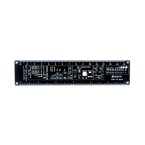
The 7Semi PCB Ruler is a multi-purpose tool designed for electronics engineers, hobbyists, and PCB designers. It works as both a measuring ruler and a quick reference guide for common electronic components. The board includes markings for different SMD package sizes, transistor types, connectors, and pin layouts, helping you easily identify and compare components during design or assembly. Its compact and sturdy PCB design makes it easy to carry and use on your workbench. This tool is very useful for PCB design, debugging, prototyping, and learning electronics.
Features:
• Measurement Scale (0 to 15 IN CMs): Built-in ruler markings for quick and accurate measurement.
MD Transistors: SOT23, SOT89, SOT223, SOT252, SC70
MELF & Micro MELF Packages
IC Packages:
– SSOP, SOIC, TSSOP-64
– Reference of QFN, DFN, QFP footprints
– QFP (10×10, 14×14 with 0.5mm & 0.8mm pitch)
• SMD Package Reference: Shows common SMD sizes for easy identification.
• Component Guide: Includes transistor types, LED polarity, and other useful references.
• Connector Reference: Displays common connector footprints and layouts.
• Pinout Guide: Helps in quickly checking pin spacing and arrangements.
• Compact PCB Design: Strong and portable for everyday use.
• Easy to Use: Useful for both beginners and professionals.
• Multi-Purpose Tool: Ideal for PCB design, repair, prototyping, and learning electronics.
Footprints & symbols Included:
- SMD Resistor/Capacitor Sizes: 0201, 0402, 0603, 0805, 1206, 1210, 2010, 2512
- Diode Packages: SOD323, SOD80, SOD128, SMA, SMB, SMC
- SMD Transistors: SOT23 (3 pin & 5 pin) , SOT89, SOT223, SOT252, SC70
- MELF & Micro MELF Packages
- IC Packages:
– SSOP, SOIC, TSSOP-64
– Reference of QFN, DFN, QFP footprints
– QFP (10×10, 14×14 with 0.5mm & 0.8mm pitch)
– BGA 15×15 grid - Connectors:
– JST 1.25mm (1x06)
– Qwiic 1.25mm (1x04) - Transistor Symbols: PNP & NPN
- Mosfet Symbol : PMOS & NMOS
- THT LED Polarity Marking (Anode/Cathode)
- Pin Pitch & Header Guides
- AWG Wire Size Reference (AWG 8–18)
Related Products